
White Paper
Cold-Weather Performance: Keeping Digital Signs Running in Snow and Extreme Cold
Thermal Dissipation in Sub-Zero Environments: How Weather-Sealed Outdoor Enclosures Leverage Internal Electrical Heat Currents
Executive Summary
A common misconception among facility managers and operators is that extreme sub-zero weather negatively impacts the core light-emitting technology of outdoor LED displays. In physical reality, light-emitting diodes (LEDs) are solid-state semiconductors that operate with higher optical efficiency and longer operational lifespans in cold ambient conditions.
However, deploying digital signage in sub-zero climates introduces specific mechanical and thermal challenges:
- Cold-start thermal shock on power distribution units and integrated circuit (IC) driver boards.
- Internal condensation freeze-thaw cycles inside non-sealed enclosures.
- Front-face snow and ice accumulation obstructing display visibility.
Rather than relying on high-draw auxiliary heating elements, modern outdoor LED enclosures leverage internal thermal dissipation—redirecting heat generated by power supplies, IC drivers, and diode forward voltage—to maintain a stable internal microclimate. This paper examines the physics of semiconductor behavior in freezing temperatures, the mechanics of self-sustaining thermal loops within IP-rated weather-sealed enclosures, and best practices for sub-zero operational reliability.
The Engineering Reality: Cold Weather & LED Efficiency
Semiconductor Physics at Sub-Zero Temperatures
Unlike incandescent or liquid-crystal display (LCD) technologies—which suffer from severe sluggishness or total liquid crystal freezing at temperatures below ()—LEDs excel in low ambient temperatures.
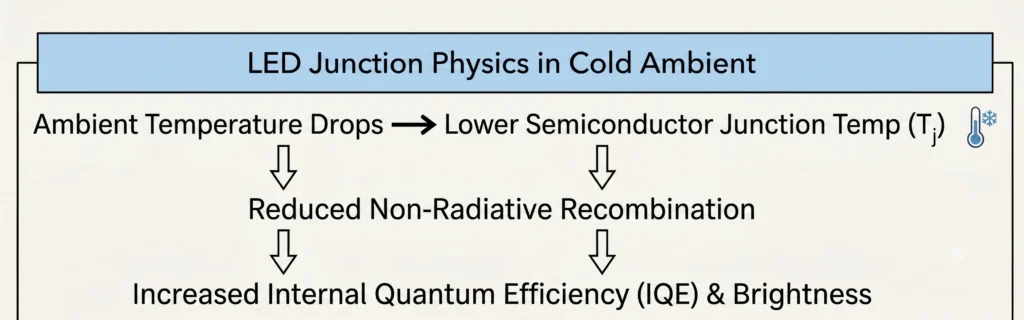
- Internal Quantum Efficiency (IQE): As ambient temperature drops, the junction temperature () of the LED diode decreases. Lower junction temperatures reduce non-radiative recombination rates, increasing the overall photon extraction efficiency of the semiconductor.
- Forward Voltage & Heat Dissipation: While forward voltage () slightly increases at lower temperatures, the overall thermal stress on the diode substrate is significantly reduced, slowing the rate of lumen depreciation and extending total operational lifespan.
Primary Structural & Operational Challenges in Freezing Climates
While the LEDs themselves benefit from the cold, surrounding electronic and mechanical components face specific failure modes if unmitigated:
- Moisture Ingress and Dew Point Trapping: When ambient air inside a non-sealed cabinet cools rapidly, ambient moisture condenses on cold internal surfaces. In sub-zero conditions, this condensation freezes, leading to trace-line corrosion, shorts, and mechanical expansion stress on soldered connections.
- Inrush Current & Thermal Shock During Cold Starts: Powering on electronic components from a “dead cold” state (e.g., ) subjects power capacitors and driver ICs to severe thermal expansion stress as currents rapidly elevate internal component temperatures.
- Face-Mask Ice Accumulation: Wind-driven snow and freezing rain can collect on module louvers. Without sufficient forward thermal radiation from within the cabinet, ice buildup obscures pixel visibility and distorts beam angles.
Thermal Dissipation & Internal Microclimates
The Physics of Internal Heat Generation
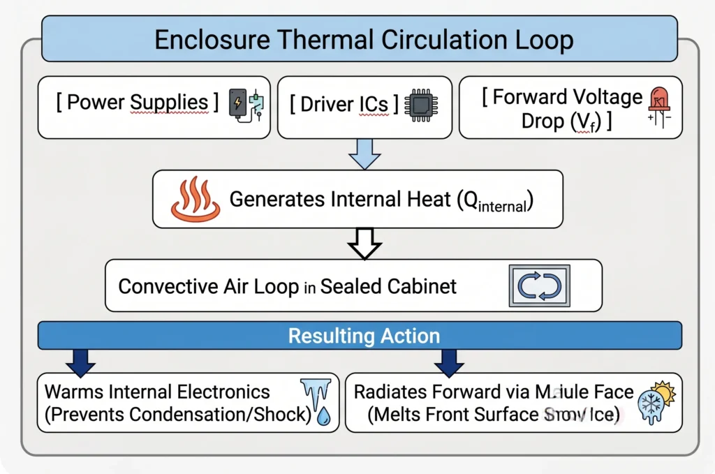
An outdoor LED display enclosure is an active electrical ecosystem. When operating, heat is generated primarily by three main hardware subsystems:
- AC/DC Switching Power Supplies: Convert incoming alternating current to low-voltage direct current (typically 4.2V–5V), operating at efficiency. The remaining of total power consumption is dissipated directly into the enclosure as sensible heat.
- Integrated Circuit (IC) LED Drivers: Constant-current driver ICs regulate power delivery to individual diode channels. Electrical resistance within these drivers converts energy into localized ambient thermal radiation.
- Diode Forward Voltage Drop (): While a portion of the electrical energy supplied to the LED chip is emitted as visible light (photons), the remaining energy is converted to thermal energy at the semiconductor junction ().
Where represents total system power consumption and represents the overall luminous efficacy ratio of the system.
Leveraging Self-Sustaining Thermal Loops
In sub-zero conditions, rather than venting this thermal energy or relying on power-hungry auxiliary ceramic heaters, a sealed cabinet enclosure acts as a passive heat exchanger:
- Convective Thermal Recirculation: Air warmed by power distribution units rises and circulates across the rear of the LED modules, creating an internal microclimate.
- Mitigating Auxiliary Power Costs: Traditional heating elements can require per square meter of extra power draw. Utilizing system-generated heat maintains the internal ambient temperature within safe operational thresholds (typically above inside the cabinet during an active exterior freeze) without incremental energy expenditure.
Ingress Protection (IP) & Moisture Isolation
To ensure internal thermal currents remain effective, the enclosure must maintain strict ingress protection against external atmospheric interaction.
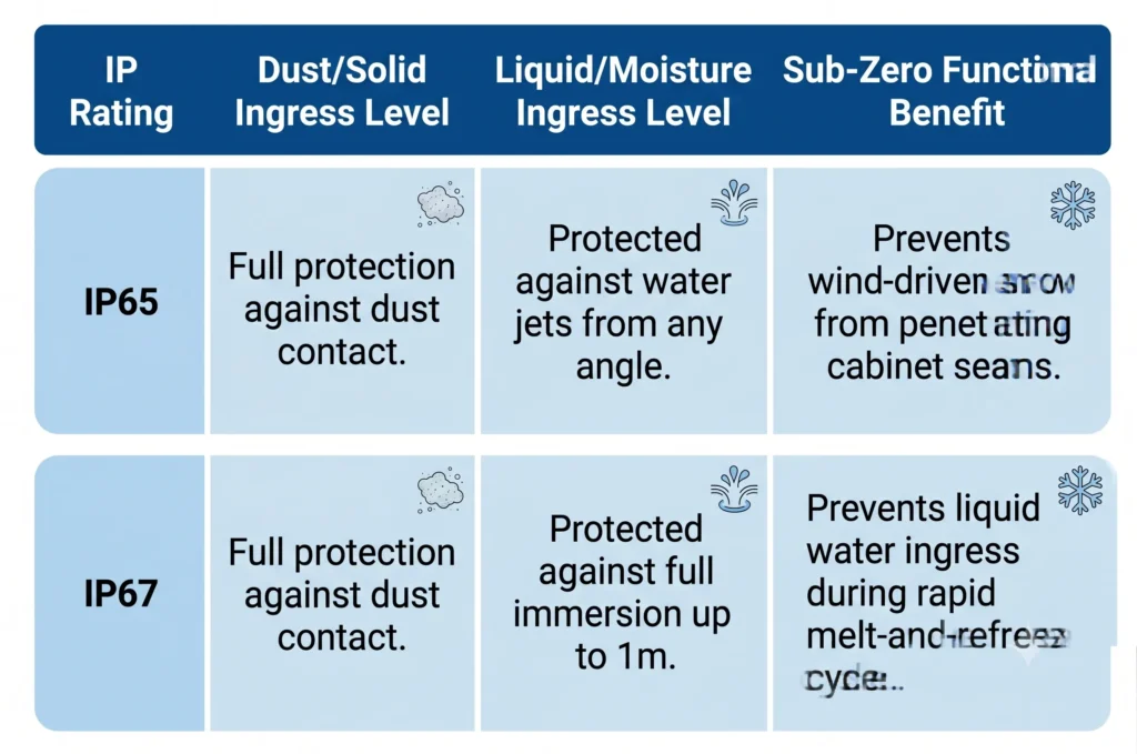
A minimum rating of IP65 on the front face and IP67 on sealed sub-components prevents external humidity from crossing the boundary into the internal microclimate, completely eliminating internal frost formation on sensitive Printed Circuit Board (PCB) traces.
Operational Best Practices for Sub-Zero Deployments
Power Management: Continuous Low-State vs. Cold Starts
The most critical operational strain on electronic components in sub-zero climates occurs during a “cold boot”—powering on system electronics after prolonged exposure to sub-zero ambient temperatures while in a completely de-energized state.
- Risk of Cold Boots: Applying full voltage to cold capacitors, transformers, and solder joints induces rapid thermal expansion (). Over repeated cycles, differential thermal expansion between copper traces, FR-4 PCB substrates, and lead-free solder alloys induces micro-fracturing (fatigue failure).
- Mitigation Strategy (Continuous Trickle State): Operating the display with a baseline power load—even when no active image is displayed (e.g., maintaining a low-level black or ambient background signal)—keeps switching power supplies active. This maintains a baseline internal temperature of above ambient, entirely bypassing the risk of cold-start thermal shock.
Front-Face Passive Defrosting Dynamics
Snow and ice accumulation on the exterior face of an LED display can obscure content and place mechanical weight on module louvers.
- Conductive Heat Transfer: Thermal energy generated at the diode junction () conducts forward through the aluminum or specialized polycarbonate heat-sink housing of the module mask.
- Passive Clearing: Heat radiating through the front surface of the display raises the surface temperature of the polycarbonate louvers slightly above (). This thermal transfer prevents ice bonding, allowing fresh snow to slip off the module face passively without requiring manual clearing or mechanical scraping.
Limitations and Statement on Evidence
This white paper is based on publicly available technical standards, industry research, and established engineering principles related to outdoor electronic systems. Performance outcomes may vary depending on site conditions, materials, and system configuration. This document is intended for technical evaluation and comparative analysis and does not constitute a performance guarantee.
References & Industry Standards Cited
Schubert, E. F. (2006). Light-Emitting Diodes (2nd ed.). Cambridge University Press. (Chapter 5: “Internal Quantum Efficiency and Junction Temperature Dynamics”).
U.S. Department of Energy (DOE). Solid-State Lighting R&D Plan: Thermal Management in Outdoor Luminaires and Displays.
IEEE Transactions on Device and Materials Reliability. Effects of Low-Temperature Cycling on Solder Joint Integrity in Outdoor Power Electronics.
IPC (Association Connecting Electronics Industries). IPC-CC-830: Qualification and Performance of Electrical Insulating Compound for Printed Wiring Assemblies.
Illuminating Engineering Society (IES). LM-80-15: Measuring Luminous Flux and Color Maintenance of LED Packages, Arrays, and Modules at Temperature Extremes.
Incropera, F. P., DeWitt, D. P., Bergman, T. L., & Lavine, A. S. (2007). Fundamentals of Heat and Mass Transfer (6th ed.). John Wiley & Sons. (Section 4.3: “Conductive Heat Transfer in Solid-State Electronics”).
International Electrotechnical Commission (IEC). IEC 60529: Degrees of Protection Provided by Enclosures (IP Code).
National Electrical Manufacturers Association (NEMA). NEMA 250: Enclosures for Electrical Equipment (1000 Volts Maximum).
IPC Association. IPC-A-610G: Acceptability of Electronic Assemblies (Chapter 8: “Component Solder Joint Fatigue and Thermal Cycling Dynamics”).
ASHRAE. Handbook—Fundamentals: Chapter 1: Psychrometrics and Condensation Control in Enclosed Structures.
Fast Facts
Sub-Zero Efficiency Gain Unlike traditional displays, solid-state LED junction efficiency increases in sub-zero temperatures, delivering higher optical output per watt without additional power draw.
Self-Sustaining Thermal Loop Internal heat generated by power supplies, IC drivers, and diode forward voltage creates a natural convection loop inside sealed cabinets, maintaining operational microclimates without energy-intensive heaters.
Ingress & Condensation Barrier IP65/IP67 weather-sealed enclosures prevent wind-driven snow penetration and eliminate internal moisture accumulation during rapid freeze-thaw cycles.
Frequently Asked Questions
What is the lowest temperature an outdoor LED sign can operate in?
Standard commercial-grade outdoor LED signs are typically rated for ambient operating temperatures between and ( to ). However, solid-state LED modules designed with sealed IP65/IP67 enclosures and continuous thermal power loop strategies can reliably operate in extreme environments down to () or lower without component failure.
Do extreme sub-zero temperatures cause LED lights to dim or fail?
No. Unlike traditional fluorescent lamps or LCD panels—which experience severe dimming or slow liquid crystal response times in freezing weather—LED semiconductors actually experience increased optical efficiency and higher brightness at lower temperatures. Cold conditions reduce junction heat, lowering the rate of lumen degradation and extending the diode’s overall lifespan.
Will heavy snow and freezing ice damage the front of an LED display?
Physical damage is rare if the display utilizes impact-resistant polycarbonate louvers and weather-sealed modules. Furthermore, heat generated during normal electrical operation conducts forward through the LED module face. This mild surface heat keeps the face mask slightly above freezing, preventing heavy ice bonding and allowing dry snow to slide off passively.
Is an internal auxiliary heater necessary for LED signs installed in cold climates?
In most cases, dedicated internal space heaters are unnecessary and add unneeded energy costs. A fully weather-sealed cabinet captures the waste heat naturally produced by the sign’s internal switching power supplies, receiver cards, and driver ICs. This self-generated thermal energy maintains a safe internal microclimate during operation, eliminating the need for supplemental heating units.
What causes an LED sign to fail during a winter cold-start?
When an electronic sign is completely powered off in sub-zero conditions and then suddenly turned on, the rapid transition from cold to hot induces sharp thermal expansion (). This differential thermal expansion strains solder joints, capacitors, and PCB traces, potentially causing micro-fractures. Maintaining a continuous standby baseline power load keeps internal components warm and prevents cold-start thermal shock.