
White Paper
Why Is Half My LED Sign Black?
Modular Serviceability Standards: Minimizing Diagnostic Downtime Through Segmented Hardware Architecture
Executive Summary
When a commercial digital display experiences a partial outage—such as half of the display turning completely black—the issue disrupts messaging and creates immediate operational friction. A localized failure in an LED display rarely stems from a widespread failure of individual light-emitting diodes. Instead, it signals a disruption in the underlying power distribution network or serial signal chain.
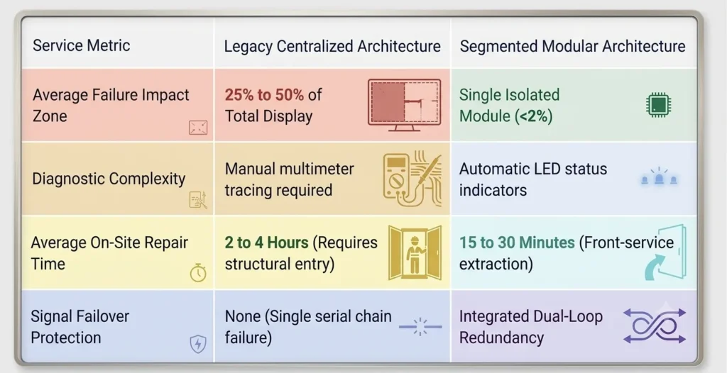
Historically, legacy display architectures relied on centralized power supplies and daisy-chained data connections. Under this design, a single component failure (such as a blown fuse, compromised ribbon cable, or failed receiving card) cascades through downstream components, taking down large sections of the display.
This technical paper analyzes the underlying electrical and data-routing mechanisms behind partial screen blackouts. It evaluates the shift toward segmented, modular hardware architectures designed to isolate failures, simplify field diagnostics, and reduce Mean Time to Repair (MTTR).
Mechanics of a Partial Display Outage
Commercial LED displays are built from a grid of individual LED modules managed by power supply units (PSUs) and receiver/video cards. When exactly half or a distinct geometric block of a display goes dark, the root cause usually falls into one of three hardware categories:
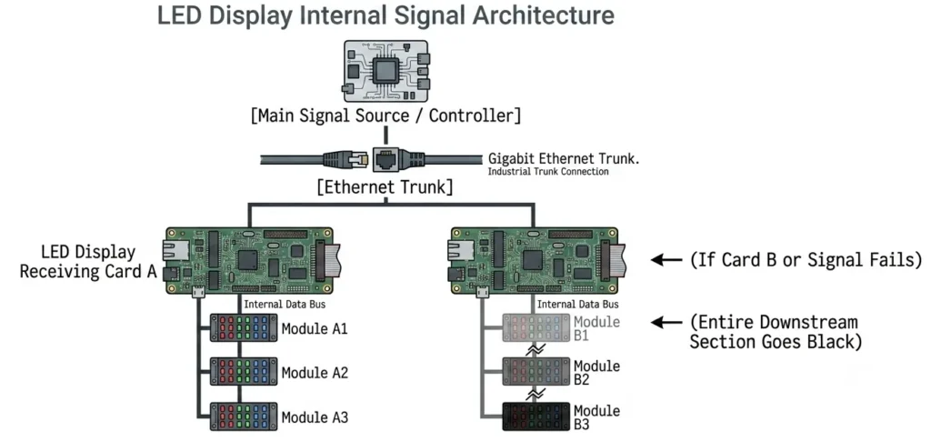
A. Serial Signal Chain Interruption
LED data routing functions like a chain. Video processing cards feed data to primary receiving cards, which pass data sequentially to adjacent cards or modules via ribbon cables or RJ45 patch cables.
- The Failure Point: If receiving card $B$ loses power or fails internally, it stops passing data to every module downstream.
- The Symptom: The display works normally up to the physical boundary of receiving card $A$, while all modules connected to receiving card $B$ and beyond turn completely black.
B. Power Supply Unit (PSU) Trunk Failures
Direct-current (DC) power supplies convert incoming AC utility power (120V/240V) to low-voltage DC (typically 4.2V–5V) required by LED driver ICs.
- The Failure Point: In cost-optimized legacy displays, a single high-wattage PSU may power an entire vertical or horizontal section of modules.
- The Symptom: If a PSU fails, trips its thermal overload, or loses its AC feed, every module linked to that specific power bus turns dark immediately.
C. Thermal Stress and Solder Trace Fatigue
Digital displays installed outdoors endure continuous thermal cycling. Operating temperatures fluctuate based on internal heat generation and external ambient exposure.
The Failure Point: Differential expansion between circuit board substrates and copper traces can cause micro-fractures in solder joints or ribbon connector pins.
The Symptom: Intermittent connection loss at the primary signal input pin of a module strip, causing an entire section to drop out once internal cabinet temperatures cross a critical threshold.
Diagnosing Sectional Failures
Field service technicians historically relied on manual multi-meter resistance testing and systematic cable swap routines to locate hardware faults. Modern diagnostic procedures focus on identifying the precise boundary where communication or power drops off.
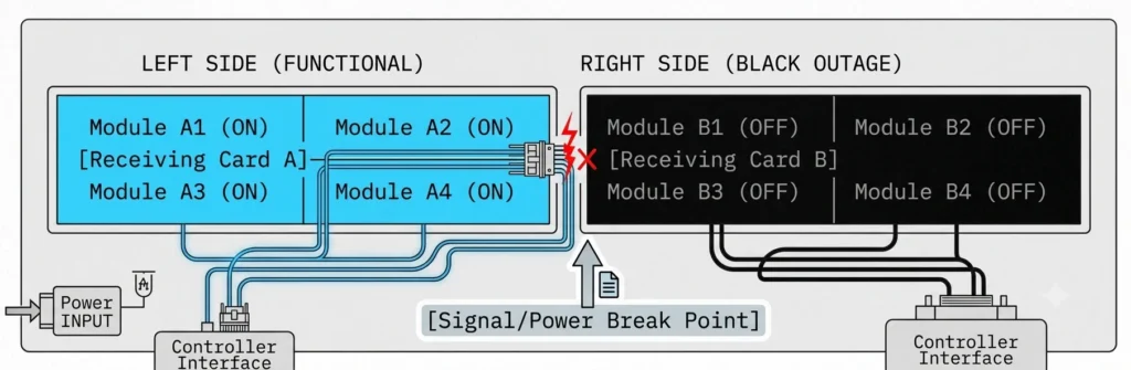
Diagnostic Sequence
- Map the Outage Boundary: Identify the exact module where the active display meets the dark region. The failure almost always lies within the last working module or the first dark module in the control sequence.
- Inspect Diagnostic LEDs: Receiving cards feature status indicator LEDs. A rapid green flash indicates normal signal reception and processing. A slow flash or solid light indicates a loss of upstream signal or a configuration mis-match.
- Verify DC Output Voltage: Use a digital multimeter across the $V+$ and $V-$ terminal blocks of the PSU powering the unlit zone. A reading of $0.0\text{ V DC}$ confirms power supply failure, whereas a steady $5.0\text{ V DC}$ reading indicates the issue lies in signal transmission or module driver logic.
Engineering Solutions: Segmented Hardware Architecture
To eliminate large-scale display outages and lower long-term service costs, modern display engineering has shifted away from single-point-of-failure topologies toward Segmented Hardware Architecture.
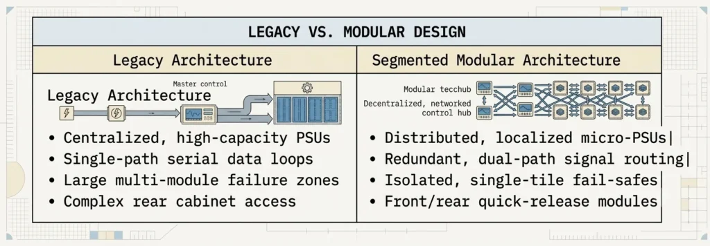
Key Architectural Pillars
1. Isolated Distributed Power Banks
Instead of running a large display section off a single massive power supply, segmented architecture divides the display into smaller power zones. Each zone uses dedicated, lower-wattage PSUs configured in parallel. If one unit fails, the outage is isolated to a small, localized cluster rather than an entire half or quadrant of the screen.
2. Dual-Loop Signal Redundancy
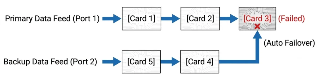
To prevent serial chain failures from taking down downstream modules, advanced displays use dual-receiving loop topologies.
Signal enters the display network from both ends of the chain simultaneously (Primary Line A and Secondary Line B). Under normal conditions, Line A processes the data. If a cable is damaged or a receiving card drops offline midway through the display, the receiving cards automatically switch to Line B within milliseconds. This failover preserves full-screen operation until scheduled maintenance occurs.
3. Tool-less Front-Service Modularization
Legacy display maintenance often required opening heavy rear cabinet doors, unbolting structural frames, and manually removing dozens of delicate ribbon connectors.
Segmented modular architecture uses self-contained LED tiles equipped with integrated power/data bridge connectors and magnetic or quick-turn latching mechanisms. Technicians can extract and replace a faulty module from the front of the display using a specialized suction or key tool in under two minutes, avoiding costly bucket-truck dispatches or extended structural teardowns.
Quantifying Downtime & Maintenance Efficiency
Implementing a segmented hardware design directly impacts total cost of ownership (TCO) and operational uptime.
Mean Time to Repair (MTTR) can be calculated using the formula:

Conclusion
A half-black LED display is rarely a sign of total system failure. Instead, it is a predictable outcome of single-path signal routing or centralized power distribution.
By transitioning to a segmented hardware architecture—supported by distributed power, signal redundancy, and modular component design—display operators can effectively eliminate widespread section outages, simplify routine field maintenance, and maximize display uptime over the system’s operational lifespan.
References
Signal Topology & Protocol Layering:
ISO/IEC 7498-1 (OSI Reference Model): Used to cite physical and data link layer vulnerabilities in single-ended serial communication vs. redundant topology.
TIA/EIA-485 (RS-485 Standard): The physical layer standard governing differential signaling, noise immunity, and daisy-chain topology limits in digital displays.
Reliability & Dependability Metrics (MTTR / MTBF):
IEC 60050-192:2015 (International Electrotechnical Vocabulary – Dependability): Formally defines “Active Repair Time,” “Fault Localization,” and “Mean Time to Repair” (MTTR) as standardized maintainability metrics.
MIL-HDBK-217F / Telcordia SR-332: Reliability prediction models for electronic equipment, establishing how thermal stress directly accelerates component degradation (Arrhenius rate model).
Power Distribution & Environmental Design:
IEEE 1413: Standard methodology for reliability predictions of hardware assemblies.
IEC 60529 (Ingress Protection): Governs enclosure sealing, moisture isolation, and thermal dissipation constraints in outdoor display hardware.
Fast Facts
- Root Cause: Partial screen blackouts are rarely caused by dead LEDs; they stem from a break in the DC power supply network or the serial signal chain.
- The Demarcation Rule: The physical hardware failure is almost always located right at the boundary line—either in the last working module or the first dark module.
- Modern Solution: Upgrading to a segmented, modular architecture prevents single-point component failures from taking down large sections of a display, dramatically reducing repair downtime.