
White Paper
Why Won't My Computer Connect to My LED Sign?
Network Isolation and Port Configuration: Resolving Router and Firewall Communication Handshakes in Cloud-Managed Displays
Executive Summary
When an operator cannot connect to a cloud-managed commercial LED display, the system is rarely suffering from a total physical hardware failure. Instead, the breakdown almost always occurs during the network-level communication handshake.
Modern commercial digital displays rely on continuous bidirectional communication between cloud servers, local control units, and management software. Enterprise network security controls—such as isolated VLANs, blocked outbound ports, strict firewall rules, and aggressive router security profiles—frequently intercede during these handshakes.
This technical paper breaks down the network routing mechanics behind display connectivity drops, isolates the primary firewall and router configuration hurdles, and provides a structured engineering workflow to establish secure, reliable display communications.
Anatomy of the Network Handshake
To understand why a computer or cloud platform fails to establish a connection with an LED controller, it is essential to trace how a digital display communicates across a network infrastructure.
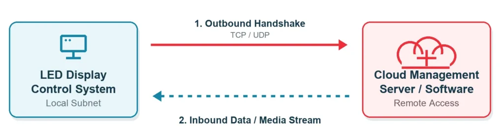
Commercial displays utilize two primary connection architectures:
Local Area Network (LAN) Peer-to-Peer: The management computer and the display controller reside on the same local subnet. Communication relies on local IP address routing and unblocked internal network traffic.
Cloud-Managed Outbound Architecture: The display controller inside the sign initiates an outbound TCP socket connection (IETF RFC 793) to a cloud platform. The user’s computer communicates with the cloud interface, which routes content commands back down through the established socket tunnel.
When a handshake fails, it typically halts at one of three critical layers: IP assignments, port blocking, or virtual network isolation.
Primary Network Failure Points
1. VLAN Isolation and Subnet Mismatches (IEEE 802.1Q)
Enterprise networks (such as those in school districts, corporate campuses, and municipal systems) separate traffic using Virtual Local Area Networks under the IEEE 802.1Q standard.
The Problem: Direct local communication fails if the management PC is connected to an enterprise workstation VLAN (e.g.,
192.168.10.x) while the LED controller is assigned to a guest or IoT isolation VLAN (e.g.,192.168.50.x).The Result: The router intentionally drops Layer 2/3 packets attempting to traverse the VLAN boundary unless explicit inter-VLAN routing and access control list (ACL) rules permit the connection.
2. Blocked Outbound Ports & Firewall Filtering (NIST SP 800-41)
Cloud-managed displays rely on specific transmission protocols (such as standard HTTPS, custom TCP sockets, or WebSocket connections) to maintain an open control tunnel.
The Problem: As defined in NIST SP 800-41 (Guidelines on Firewalls and Firewall Policy), strict enterprise perimeter firewalls default to blocking all non-essential outbound traffic or enforcing stateful packet inspection (SPI) that drops long-polling TCP connections.
The Result: The controller cannot register its online status with the cloud server, causing management software to report the display as “Offline” even though physical network links are fully active.
3. Dynamic IP Instability (IETF RFC 2131)
Network routers reassign dynamic IP addresses based on Dynamic Host Configuration Protocol (DHCP) lease timers.
The Problem: Under IETF RFC 2131, if an LED controller is assigned an unreserved dynamic IP address, a router reboot or lease expiration will result in a new IP address assignment.
The Result: Control software configured to communicate with the initial IP address loses direct contact immediately upon lease renewal.
Technical Diagnostic Sequence
When troubleshooting connectivity failures between a local network/computer and an LED display, field technicians and network administrators should follow this systematic protocol:

Step 1: Verify Layer 1 & 2 Link Integrity
Confirm active link LED lights on the display controller’s RJ45 Ethernet port (or confirm signal strength on cellular/Wi-Fi hardware).
Ensure link speed negotiates correctly (typically 100Mbps or 1Gbps full-duplex).
Step 2: Test Subnet Reachability via ICMP Ping
Open a terminal interface on the local management computer and attempt to ping the display’s IP address:
Success: A stable response confirms physical connectivity and basic IP routing on the local subnet.
Failure (Request Timed Out): Confirms an IP assignment conflict, subnet mask mismatch, or complete VLAN block between the PC and the sign.
Step 3: Audit Communication Ports (Telnet / Port Diagnostic)
Test specific control and communication ports to verify they are open through the router and firewall:
If port connection tests fail while general pings succeed, an internal firewall rule is actively filtering required communication ports.
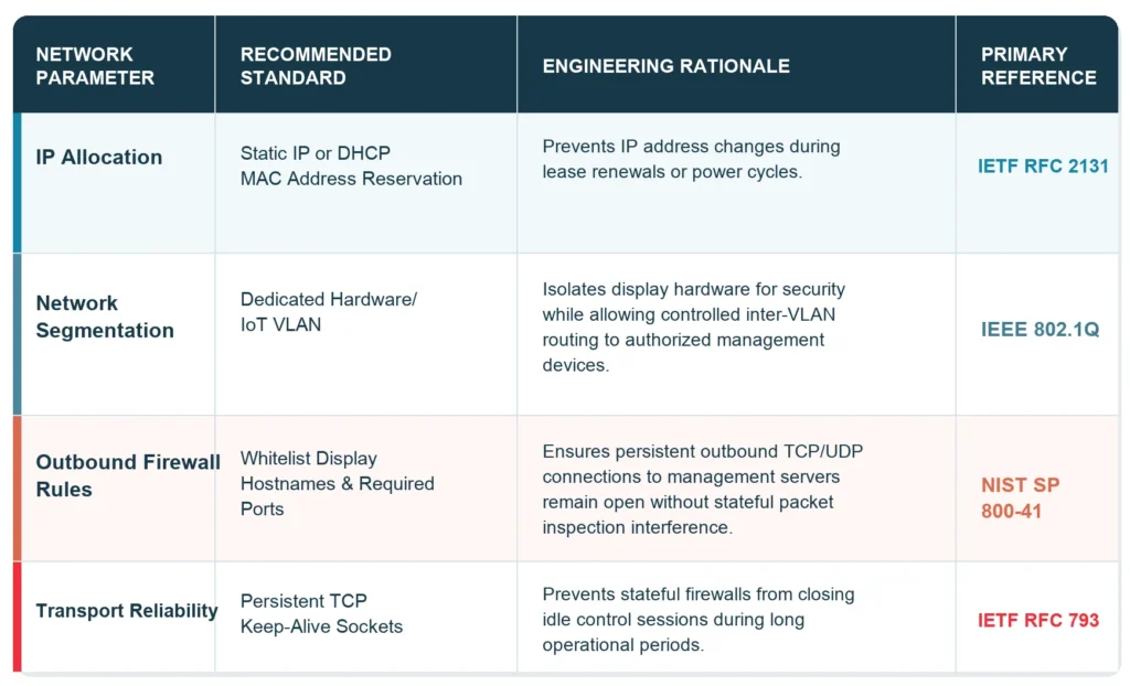
Recommended Architecture & Configuration Standards
To ensure permanent, uninterrupted display communication across corporate and institutional networks, deploy the following configuration standards:
Limitations and Statement on Evidence
This white paper is based on publicly available technical standards, industry research, and established engineering principles related to outdoor electronic systems. Performance outcomes may vary depending on site conditions, materials, and system configuration. This document is intended for technical evaluation and comparative analysis and does not constitute a performance guarantee.
References & Cited Standards
IETF RFC 793: Postel, J. “Transmission Control Protocol (TCP) Specification.” Internet Engineering Task Force (IETF).
IETF RFC 2131: Droms, R. “Dynamic Host Configuration Protocol (DHCP).” Network Working Group, IETF.
IEEE 802.1Q: Institute of Electrical and Electronics Engineers. “IEEE Standard for Local and Metropolitan Area Networks—Bridges and Bridged Networks (VLAN Tagging & Virtual Bridged Local Area Networks).”
NIST SP 800-41 Rev. 1: National Institute of Standards and Technology. “Guidelines on Firewalls and Firewall Policy.” U.S. Department of Commerce.
Fast Facts
- Primary Cause: Most computer-to-display connection failures stem from network router security policies, port filtering, or VLAN isolation rather than physical hardware component defects.
- The Outbound Rule: Cloud-managed displays rely on client-initiated outbound TCP socket tunnels; per NIST firewall guidelines, blocking these specific outbound ports marks the display as “Offline”.
- Best Practice: Assigning a DHCP MAC reservation (RFC 2131) and configuring dedicated 802.1Q inter-VLAN routing guarantees stable, long-term display connectivity across enterprise networks.
Frequently Asked Questions
Why does my sign show as offline in the cloud software if the Ethernet light is blinking?
A blinking link light indicates physical connection (Layer 1/2), but it does not mean application data is passing. Per NIST SP 800-41 guidelines, perimeter firewalls often block non-standard outbound ports, preventing the controller from establishing its TCP handshake with the cloud server.
Do I need a static public IP address for my LED display?
No. Modern cloud-managed displays use outbound connections to establish a secure tunnel back to the server. You only need a static local IP address or DHCP reservation (RFC 2131) on the internal network so local routers can reliably route local traffic.
Can an LED display operate on a corporate Wi-Fi network?
While technically possible, enterprise Wi-Fi networks often enforce client isolation, dynamic IP reassignments, and periodic re-authentication prompts that disconnect unattended hardware. A wired Ethernet connection on a dedicated IEEE 802.1Q VLAN is always recommended for mission-critical displays.